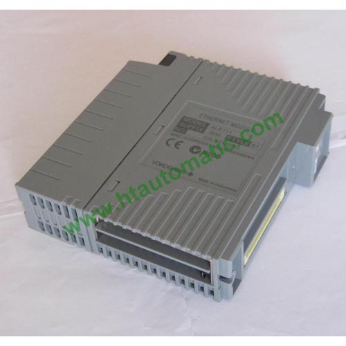
YOKOGAWA ALE111 Ethernet Communication Module (1-Port, 10 Mbps), Used in FIO System for AFV10□
(ALE111 Card, YOKOGAWA ALE111 Card, YOKOGAWA ALE111 Module)
Ordering Examples:
ALE111-S50
ALE111-S51
ALE111-SE0
ALE111-SE1
Old Ordering Examples:
ALE111-S00
ALE111-S01
ALE111-S10
ALE111-S11
The FIO is an I/O system that is connected to a control station via ESB or ER bus. FIO consists of two types of node units on two types of buses.
The node units on an ESB bus referred to as local nodes, and those on an ER bus referred to as remote nodes. Each of these nodes is composed of a base unit, power supply module, bus interface module, and input/output modules. Power supply module, bus interface module, and input/output modules can be configured redundantly.
Limitations of Installing the ALR111, ALR121, ALE111, ALP111, ALF111, AGS813 and AGP813
Number of ALR111, ALR121, ALE111, ALP111, AGS813 and AGP813 modules per FCS:
For control function for basic field control unit: 8 max. (4 pairs for dual-redundant operation) per FCS
For extended type 16 max. (8 pairs for dual-redundant operation) per FCS Number of ALF111 modules per FCS
For control function for basic field control unit: 30 max. (15 pairs for dual-redundant operation) per FCS For extended type 32 max. (16 pairs for dual-redundant operation) per FCS
Number of ALR111, ALR121, ALE111, ALP111, and ALF111 modules per ER bus train When installing on ER bus node units: 8 max. per ER bus train.