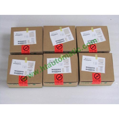
YOKOGAWA AAT141 RTD Input Module (12-channel, Isolated)
YOKOGAWA Analog I/O Modules (for FIO):
AAI135, AAI835, AAT145, AAR145, AAP135, AAI143, AAI543, AAV144, AAV544, AAT141,
AAR181, AAI141, AAV141, AAV142, AAB141, AAV542, AAI841, AAB841, AAI842, AAP149, AAP849
GENERAL
This GS covers the hardware specifications of the Analog I/O Modules (for FIO) that can be installed in the Node Unit for ESB Bus (Local Node) (ANB10S, ANB10D), the Node Unit for ER Bus (Remote Node) (ANR10S, ANR10D) and Compact Field Control Unit (for FIO) (AFF50S, AFF50D, AFV10S, AFV10D).
STANDARD SPECIFICATIONS
Current/Voltage Input Modules (Non-Isolated)
These modules mainly receive 4 to 20 mA DC or 1 to 5 V DC standardized signal from 2-wire/4-wire transmitters. They can be used in dual redundant configuration.
TC Input/RTD Input Modules (Isolated)
These modules receive signals from mV, thermocouple (TC) and RTD. They can be used in dual redundant configuration.
|
Items |
Specifications |
|
Model |
AAT141 |
AAR181 |
|
Number of input channels |
16, isolated (*7) |
12, isolated |
|
Input signal |
TC: JIS C1602:1995, IEC584:1995
Type J, K, E, B(*1), R, S, T, N
mV: -100 to 150 mV, -20 to 80 mV |
RTD: JIS C1604:1997, IEC751:1995
Pt100 (3-wire type)(*6) |
|
Switching input signals |
TC/mV can be set individually for CH1 to CH16. |
CH1 to CH12 are RTD inputs. |
|
Allowable input voltage |
±5 V |
±5 V |
|
Withstanding voltage |
Between input and system: 1500 V AC, For 1 minute |
|
Input resistance |
Power ON |
2 MΩ or more |
|
Power OFF |
2 MΩ or more |
|
Accuracy |
TC: ±30 µV
MV: ±80 µV for span (-100 to 150 mV)
±30 µV for span (-20 to 80 mV) |
RTD: ±120 mΩ |
|
Allowable total resistance of signal source plus wiring |
1000 Ω or less |
40 Ω or less (wiring resistance per wire) (*2) |
|
Effect of allowable signal source resistance (1000 Ω) |
±20 µV(*3) |
— |
|
Reference junction compensation accuracy |
Within ±1 °C (*4) (*5) |
— |
|
Measurement current |
— |
RTD: 1 mA |
|
Temperature drift |
±80 µV/10 °C (-100 to 150 mV input)
±30 µV/10 °C (TC/-20 to 80 mV input) |
±120 mΩ/10 °C (RTD input) |
|
Data update period |
1 s |
|
Burn-out |
All channels can be set together.
Setting: Not available/available (UP/DOWN)
detection time: 60 s |
|
Maximum current consumption |
450 mA (5 V DC) |
450 mA (5 V DC) |
|
Weight |
0.2 kg |
|
External connection |
Pressure clamp terminal |
|
|
|
Description |
|
Model |
AAT141 |
TC/mV Input Module (16-channel, Isolated) |
|
Suffix
Codes |
-S |
Standard type |
|
5 |
With no explosion protection |
|
E |
With explosion protection |
|
0 |
Basic type |
|
3 |
With ISA Standard G3 option and temperature (-20 to 70 °C) option |
|
Option
Codes |
/T4S00 |
With Pressure Clamp Terminal Block for Thermocouple/mV [Model: ATT4S-00] |
|
/T4S10 |
With Pressure Clamp Terminal Block for Thermocouple/mV (surge absorber) [Model: ATT4S-10] |
|
/T4D00
/T4D10 |
With Dual Pressure Clamp Terminal Block for Thermocouple/mV [Model: ATT4D-00] |
|
With Dual Pressure Clamp Terminal Block for Thermocouple/mV (surge absorber) [Model: ATT4D-10] |
|
/CCC01 |
With Connector Cover for MIL Cable [Model: ACCC01] |
Ordering Examples:
AAT141-S50
AAT141-S53
AAT141-SE0
AAT141-SE3
AAT141-S50/T4S00
AAT141-S53/T4S00
AAT141-SE0/T4S00
AAT141-SE3/T4S00
AAT141-S50/T4S10
AAT141-S53/T4S10
AAT141-SE0/T4S10
AAT141-SE3/T4S10
AAT141-S50/T4D00
AAT141-S53/T4D00
AAT141-SE0/T4D00
AAT141-SE3/T4D00
AAT141-S50/T4D10
AAT141-S53/T4D10
AAT141-SE0/T4D10
AAT141-SE3/T4D10
AAT141-S50/CCC01
AAT141-S53/CCC01
AAT141-SE0/CCC01
AAT141-SE3/CCC01
Old Ordering Examples:
AAT141-S00
AAT141-S03
AAT141-S10
AAT141-S13
AAT141-S00/T4S00
AAT141-S03/T4S00
AAT141-S10/T4S00
AAT141-S13/T4S00
AAT141-S00/T4S10
AAT141-S03/T4S10
AAT141-S10/T4S10
AAT141-S13/T4S10
AAT141-S00/T4D00
AAT141-S03/T4D00
AAT141-S10/T4D00
AAT141-S13/T4D00
AAT141-S00/T4D10
AAT141-S03/T4D10
AAT141-S10/T4D10
AAT141-S13/T4D10
AAT141-S00/CCC01
AAT141-S03/CCC01
AAT141-S10/CCC01
AAT141-S13/CCC01