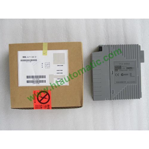
YOKOGAWA ALF111 Foundation Fieldbus Communication Module (for FIO))
MODEL AND SUFFIX CODE
|
|
|
Description |
|
Model |
ALF111 |
FOUNDATION fieldbus Communication Module |
|
Suffix
Codes |
-S |
Standard type |
|
5 |
With no explosion protection |
|
E |
With explosion protection |
|
0 |
Basic type |
|
1 |
With ISA Standard G3 option |
|
Option
Code |
/F9S00 |
With pressure clamp terminal block for Fieldbus [Model: ATF9S-00] |
Ordering Examples:
ALF111-S50
ALF111-SE0
ALF111-S51
ALF111-SE1
ALF111-S50/F9S00
ALF111-SE0/F9S00
ALF111-S51/F9S00
ALF111-SE1/F9S00
Old Ordering Examples:
ALF111-S00
ALF111-S10
ALF111-S11
ALF111-S01
ALF111-S00/F9S00
ALF111-S10/F9S00
ALF111-S11/F9S00
ALF111-S01/F9S00
ORDERING INFORMATION
Specify model and suffix codes.
For selecting the right products for explosion protection, please refer to TI 33Q01J30-01E without fail.
GENERAL
This document describes about Model ALF111 FOUNDATION fieldbus Communication Module (for FIO) which is to es- tablish communication between field control stations (FCS) and fieldbus devices compliant to the FOUNDATION fieldbus
(H1) such as transmitters and valve positioners.
This FOUNDATION fieldbus communication module can be mounted on the field control units (AFV30, AFV40, AFV10, and AFF50), ESB bus node unit (ANB10), optical ESB bus node unit (ANB11), and ER bus node
unit (ANR10).
Fieldbus power supply units (*1) and terminators are required depending on the network configuration.
HARDWARE SPECIFICATIONS
The FOUNDATION fieldbus communication module (ALF111) performs as the Link Active Scheduler (LAS) to exchange
data with devices compliant with FOUNDATION fieldbus (H1) protocol. The hardware specifications for this module are as
shown in the table below.
Hardware Specifications
|
Item |
Specifications |
|
Model |
ALF111 |
|
Interface |
FOUNDATION fieldbus (low speed voltage mode)
4 ports (1 segment (*1) per port) |
|
Transmission speed |
31.25 kbps |
|
Withstanding voltage |
From field to system: 1500 V AC/minute |
|
Bus connection (external connection) |
• Pressure clamp terminals (removable terminal block with built-in terminators that can be switched on/off.
• Connects with terminal board via a dedicated cable. |
|
Installation method |
Mounted on ANB10, ANB11, ANR10, AFF50, AFV30, AFV40, or AFV10 |
|
No. of control I/O channels (*2) |
Max. 48 points/segment
(Complies with high- and medium-speed scanning cycle by specifying up to 6 points of I/O
points as high-speed scanning type on the ER bus.) |
|
No. of fieldbus devices |
Max. 32 units per segment (*3) (ALF111 counts as one unit) (*4) |
|
Communication functions |
LAS function, Clock master function |
|
Dual-redundancy |
Enabled to set up two units of ALF111 installed in the annexed slots in the same node unit. |
|
Current consumption |
0.5 A or less |
|
Weight |
0.4 kg |
OPERATING ENVIRONMENT
Hardware Requirements
The FOUNDATION fieldbus communication module runs on the following FCS.
AFV30S, AFV30D, AFV40S, AFV40D, AFV10S, AFV10D, AFS30S, AFS30D, AFS40S, AFS40D,
AFG30S, AFG30D, AFG40S, AFG40D,
AFG81S, AFG81D, AFG82S, AFG82D, AFG83S, AFG83D, AFG84S, AFG84D, AFF50S, and AFF50D