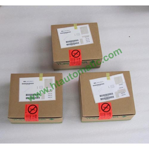
YOKOGAWA ALR121, ALR111 Serial Communication Modules (for FIO)
GENERAL
This document describes about Models ALR111 and ALR121 Serial Communication Modules (for FIO) that a field control station (FCS) uses to perform serial communication with subsystems such as FA-M3. These serial communication modules can be mounted on field control units (AFV30, AFV40, AFV10, and AFF50), ESB bus node unit (ANB10), optical ESB bus node unit (ANB11), and ER bus node unit (ANR10).
|
|
|
Description |
|
Model |
ALR111 |
Serial Communication Module (RS-232C, 2 port) |
|
Suffix
Codes |
-S |
Standard type |
|
5 |
With no explosion protection |
|
E |
With explosion protection |
|
0 |
Basic type |
|
1 |
With ISA Standard G3 option |
Ordering Examples:
ALR111-S50
ALR111-SE0
ALR111-S51
ALR111-SE1
Old Ordering Examples:
ALR111-S00
ALR111-S10
ALR111-S01
ALR111-S11
|
|
|
Description |
|
Model |
ALR121 |
Serial Communication Module (RS-422/RS-485, 2 port) |
|
Suffix
Codes |
-S |
Standard type |
|
5 |
With no explosion protection |
|
E |
With explosion protection |
|
0 |
Basic type |
|
1 |
With ISA Standard G3 option |
Ordering Examples:
ALR121-S50
ALR121-SE0
ALR121-S51
ALR121-SE1
Old Ordering Examples:
ALR121-S00
ALR121-S10
ALR121-S01
ALR121-S11
HARDWARE SPECIFICATIONS
The serial communication modules (ALR111 and ALR121) hardware specifications are as shown below.
Table Serial Communication Module Hardware Specifications
|
Item |
Specifications |
|
Model |
ALR111 |
ALR121 |
|
Interface |
RS-232C |
RS-422/RS-485 |
|
Connection method |
Point-to-point |
Point-to-point (RS-422) Multipoint (RS-485) |
|
Communication function |
Half-duplex |
|
Synchronization method |
Start-stop synchronization |
|
Transmission speed |
1200/2400/4800/9600/19200/38400 bps (*1) |
|
Transmission code |
ASCII/binary |
|
Character length |
7/8 bits |
|
Stop bit length |
1/2 bits |
|
Parity check |
None/even/odd |
|
Lag time after data transmission |
1 ms (The lag time to start receiving data again after data transmission.) |
|
Transmission distance |
Maximum 15 m |
Maximum 1200 m (total extended length) |
|
Installation method |
Mounted on ANB10£, ANB11£, ANR10£, AFF50£, AFV10£, AFV30£, or AFV40£ |
|
I/O wiring |
AKB131, AKB132, AKB133, AKB134 cables, etc. |
Cable with 3-pair shield, AKB161, or AKB162 |
|
Wiring connection |
D-sub-9-pin (female x 2) |
Clamped with terminal block’s M4 screws
(5 poles x 2) |
|
Current consumption |
0.5A |
|
Weight |
0.3 kg |
0.3 kg |
*1: The applicable transmission speed depends on the communication function, subsystems, and connection method.
An FCS collects data from subsystems or sets data with control calculations to subsystems using the builder functions
by way of serial communication modules. A communication module selects only one communication function, thus two ports must have identical communication functions. It is not possible to select different communication function
for every port. The communication functions and those transmission speeds for each communication module are as shown in the table below.
n OPERATING ENVIRONMENT
Hardware Requirements
The serial communication module runs on the following FCS.
AFV30S, AFV30D, AFV40S, AFV40D, AFV10S, AFV10D, AFS30S, AFS30D, AFS40S, AFS40D,
AFG30S, AFG30D, AFG40S, AFG40D,
AFG81S, AFG81D, AFG82S, AFG82, AFG83S, AFG83D, AFG84S, AFG84D, AFF50S, AFF50D
Software Requirements
The serial communication module runs on the control functions of the following FCS.
LFS1700 Control Function for Field Control Station (for AFV30£/AFV40£, Vnet/IP and FIO):
for AFV30£/AFV40£
LFS1500 Control Function for Field Control Station (for AFV10£, Vnet/IP and FIO): for AFV10£
LFS1300 Control Function for Standard Field Control Station (for V net and FIO): for AFS30£/AFS40£
LFS1330 Control Function for Enhanced Field Control Station (for V net and FIO):
for AFG30£AFG40£/AFG8££
LFS1350 Control Function for Compact Field Control Station (for V net and FIO): for AFF50£
n SUBSYSTEM COMMUNICATIONS
The serial communication module communicates with subsystems at the specified intervals and stores the subsystem data in the communication modules’ I/O image area. FCS accesses the communication module asynchronously from them, and refers to or sets the I/O images. This enables FCS to use the subsystem data through the I/O terminals of
the function block in the same way as the general analog and digital I/O signals.